")
")

Promociones


*
Los precios no incluyen el IVA ni la entrega
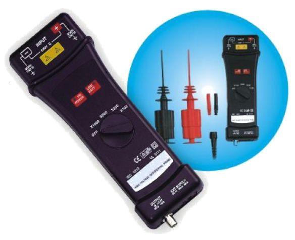
Categorías Electronica Accesorios para osciloscopios Sondas diferenciales de alta tensión Sonda diferencial RP1025D
Sonda diferencial RP1025D
En existencias
se puede enviar en 30 días